
Shader Graph is a powerful tool within Unity to modify the rendering properties of our materials. Do you want to make your surface shiny and metallic? Rusty and speckled with dirt? With Shader Graph you can, without even writing a single line of code!
Unity 2018.2 extended the ability for Shader Graph to modify the vertex positions of our meshes. Procedural animation — think rippling water, wind-swept foliage or a waving flag — can now be added to your scene with just a few extra nodes.
Let’s see how to implement a basic example of procedural vertex animation using Shader Graph.
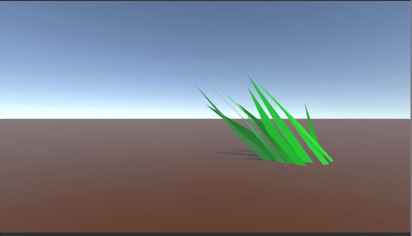
If we had a field of grass in our project, we could apply a shader to simulate a gentle breeze. With a little bit of trigonometry and a few well-placed Nodes, we can animate each mesh’s vertex positions with a gentle oscillating motion.
It’s less complicated than it sounds, so let’s jump in and get started.
Before completing this tutorial, you should:
- Have Unity 2018.2 or higher installed
- Have some familiarity with Shader Graph
Click here to check our introductory guide to ShaderGraph if you need a refresher.
PROJECT SETUP
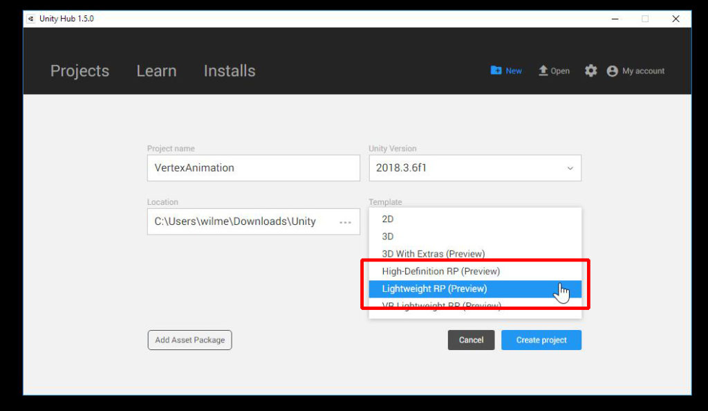
Create a new Unity project and either select the Lightweight Render Pipeline or the High-Definition Render Pipeline template.
You NEED to use the Scriptable Render Pipeline to enable Shader Graph.
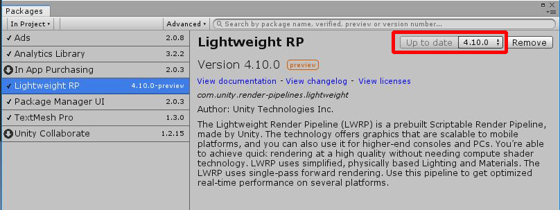
In the PackageManager (Window > Package Manager), make sure your SRP packages are up-to-date.
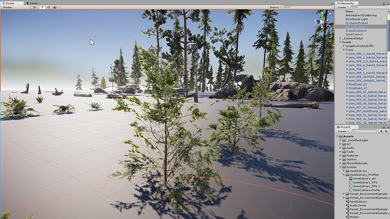
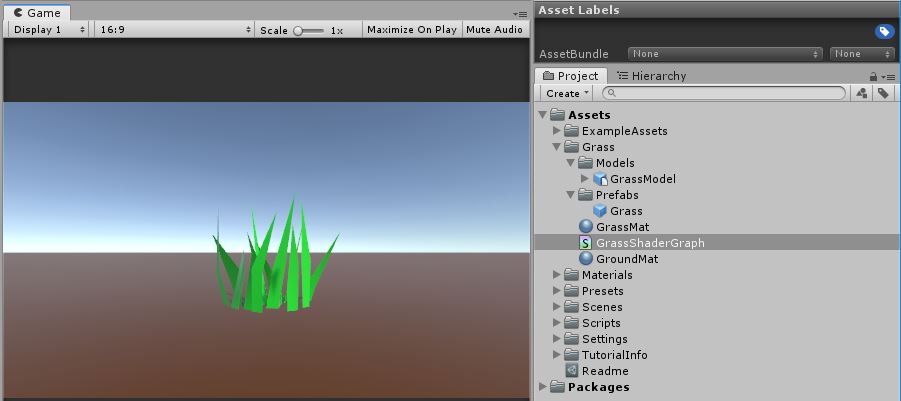
Create a new empty scene and download the sample grass model from the Resources. You can find a link to a sample asset here.
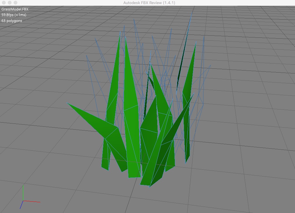
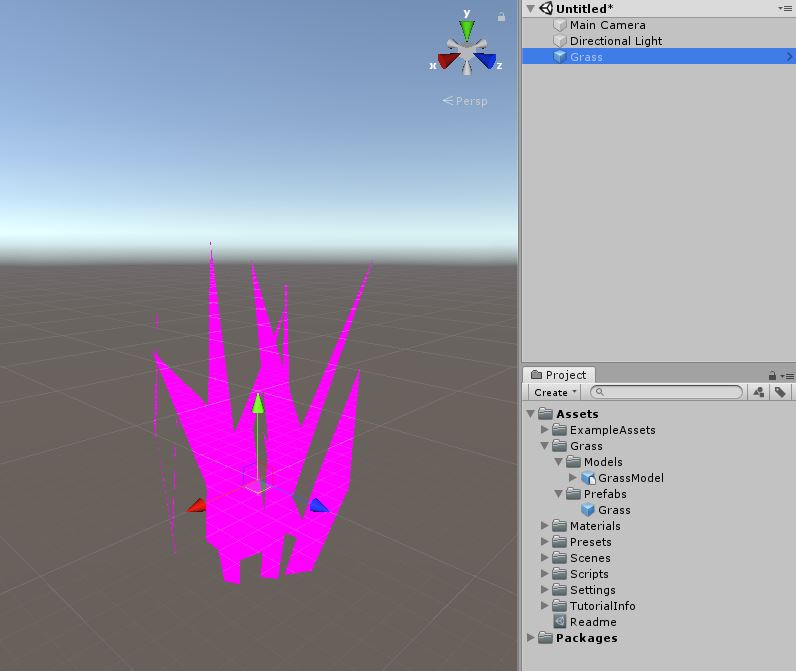
Import the model into your project as a prefab. Then drag the grass prefab into your Hierarchy window.
To keep things simple we will keep around world center. While the x and z shouldn’t matter, the y value should be 0 to keep the model at ground level.
It will be missing materials. Don’t worry! We’ll fix that shortly.
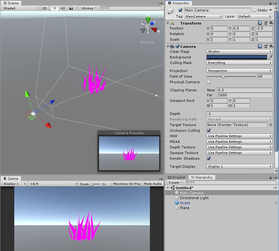
Adjust the MainCamera so our Grass object is in Game view. In this example, I have lowered the y to 0.5 and moved it in z to -2.5.
Create a plane to represent the ground. Reset its position to (0,0,0) and scale it up (10,1,10). Add a colored material to it for your visual reference.
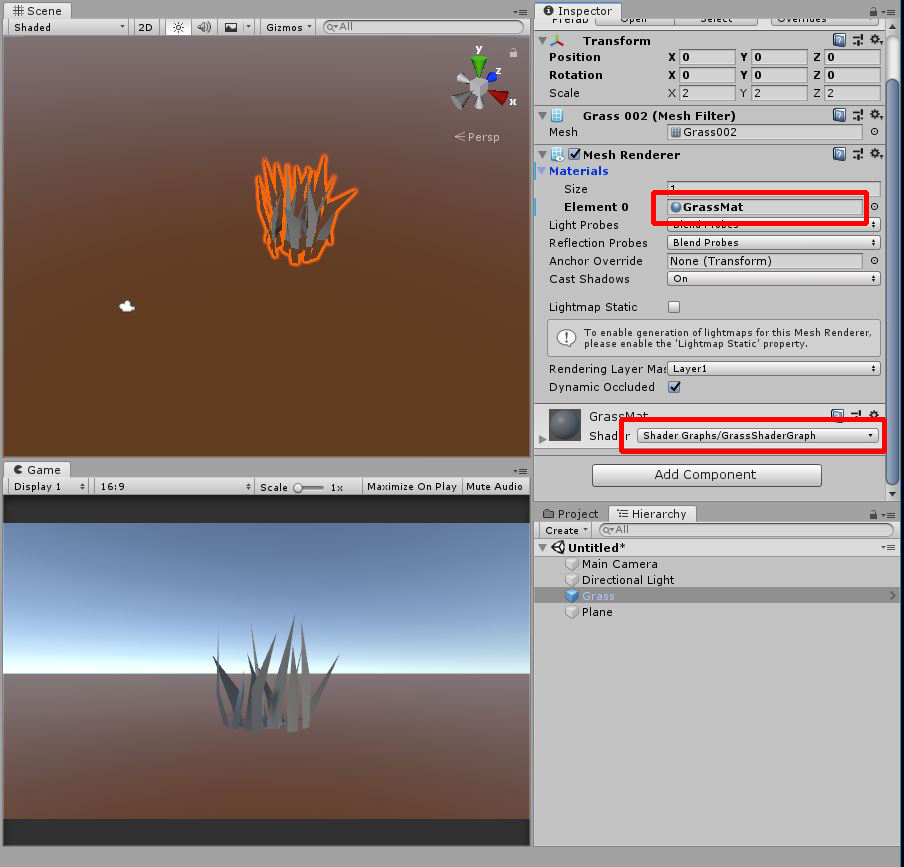
Create a new material and Shader Graph for the Grass. In my example, I will create a GrassMat material from the context menu (Create > Material) and a Shader Graph called GrassShaderGraph (Create > Shader > PBR Graph).
Assign the GrassShaderGraph to the GrassMat material’s shader.
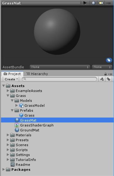
Then, apply this default gray GrassMat material to your grass Prefab’s MeshRenderer.
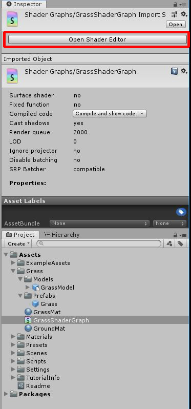
Open the Shader Editor and let’s modify the GrassShaderGraph.
SHADERGRAPH
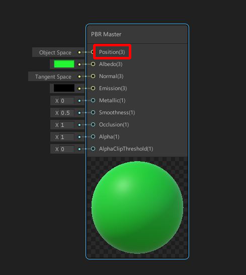
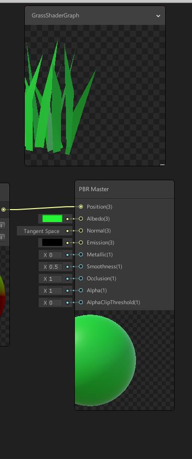
Our graph begins with a single PBR Master node. You probably are already be familiar with many of the inputs of this node. In this exercise, however, we are mostly interested in the Position input.
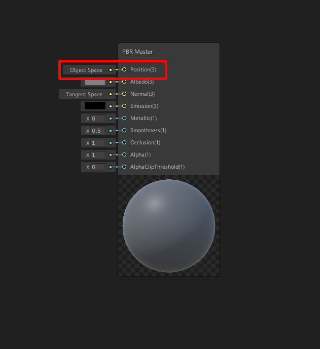
The Position input can be used to control the vertex positions of any mesh using this shader. Just as you would create nodes to alter the albedo/normal/emission/metallic properties of the material, we can use the Position input to modify the locations of a model’s vertices.
Our goal is create a set of simple math procedures to simulate some gentle swaying back and forth of our grass model.
Let’s change the Albedo to a default green color, so it resembles grass more closely.
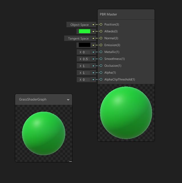
For the purposes of this exercise, we’re keeping our colors intentionally simple, but feel free to add more elaborate colors or textures to your model.
If you want to setup your Preview window, you can switch this to show your grass model. Right click and select Custom Mesh. Then select the model you want to preview.
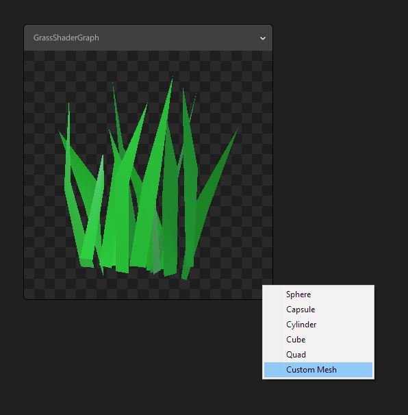
Save the Shader Graph asset and your grass model should turn green in the Scene and Game view.
POSITION NODE
The magic of vertex animation begins with the Position node.
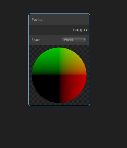
Create Node > Input > Geometry > Position
This node contains information about the existing vertex coordinates of any mesh using this material/shader combination.
Instead of colors, the Position node stores XYZ information in its red/green/blue channels respectively.
Notice how the Position node defaults to World Space.
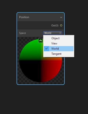
You can change the Space to:
- Object – vertex positions relative to the mesh’s pivot
- World – vertex positions relative to the world pivot
- View – vertex positions relative to the camera
- or Tangent – texture space coordinate system usually reserved for special situations.
SHIFTING VERTICES
In our example, we want the position data in World Space. We will start with the vertices at their current location in the world, perform some operation, and then feed their new positions back into the PBR Master node.
The Position input of the PBR Master expects a Vector3. Notice the (3) in parentheses next to the Input port’s label.
We’ll need to use the Split and Combine nodes so we can perform operations on the individual XYZ elements/channels from the Position node, then try to return the data as a Vector3 to the PBR Master.
Create a Split (Create Node > Channel > Split) node and a Combine node (Create Node > Channel Combine).
Connect the Position node into the Split node.
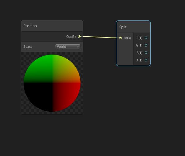
We want to separate our position data into single channels so we can work with the x, y, and z coordinates separately. The x coordinate is stored on the red layer, the y coordinate on the green layer and the z coordinate on the blue layer.
We’ll perform operations on a single channel, then turn everything back into a Vector 3 using the Combine node.
Let’s try something simple like shifting the x position side-to-side with a Math > Add node (Create Node > Math > Basic > Add)
Hook the nodes up like this.
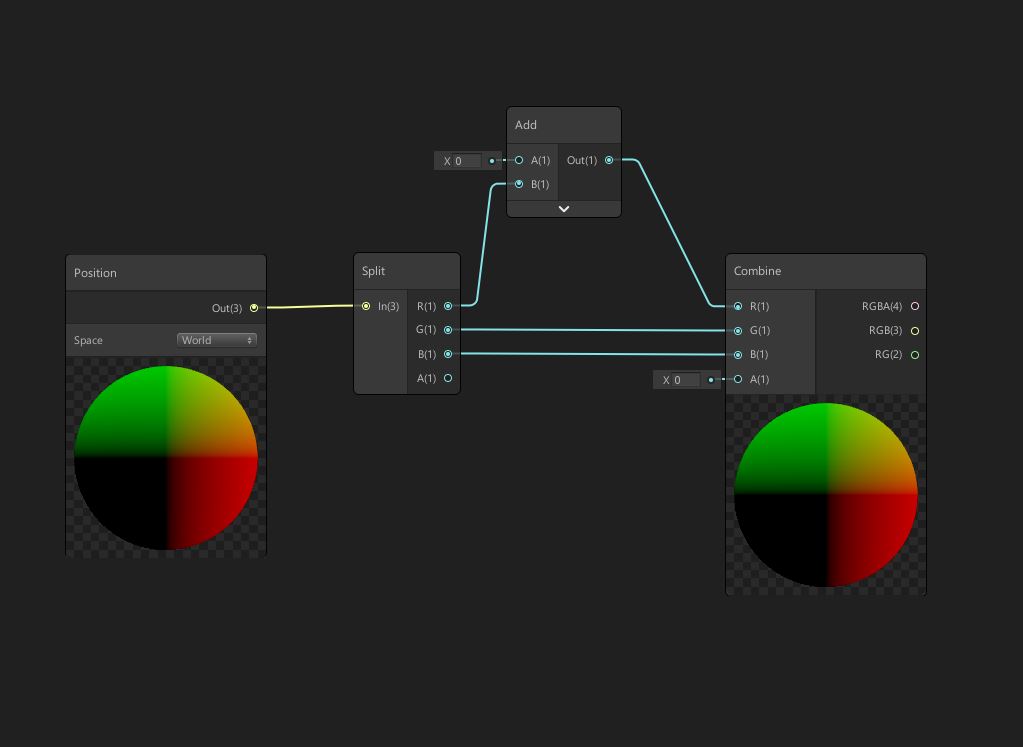
We only want to modify the x information (red channel) in our simple scenario to make the grass move side-to-side along the world x-axis. We will keep the y (green channel) and z (blue channel) exactly the same so they can connect straight through to the Combine.
Then we add some number to the x value with the Add node and connect that to the Combine.
You can either specify a static value in the Add node or create a Vector1 property on the Blackboard called OffsetX. Connect this property into the Add node. This will just be temporary to test the node’s effect.
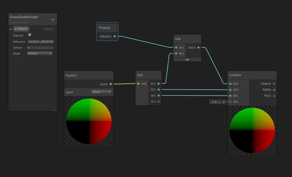
Before we send our position data back to the PBR Master, notice how the Position input expects the data in Object Space.
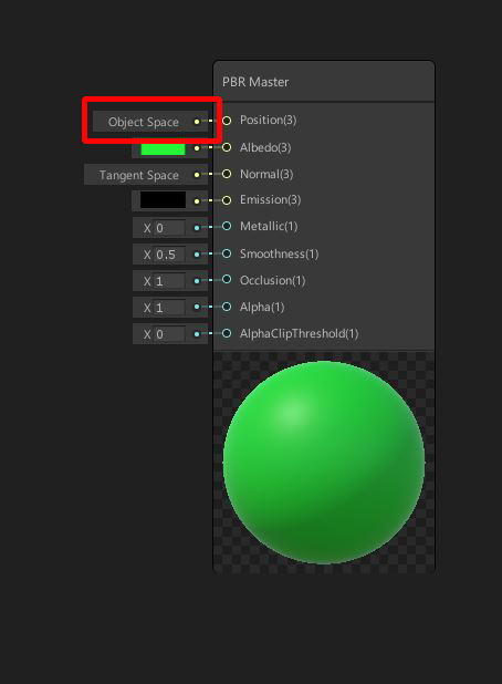
To be safe, we should convert the data to Object space using a Transform node (Create Node > Math > Vector > Transform). Connect its output back into the PBR Master node.
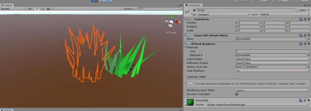
In the Inspector, we now have an exposed control called OffsetX.
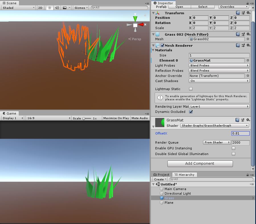
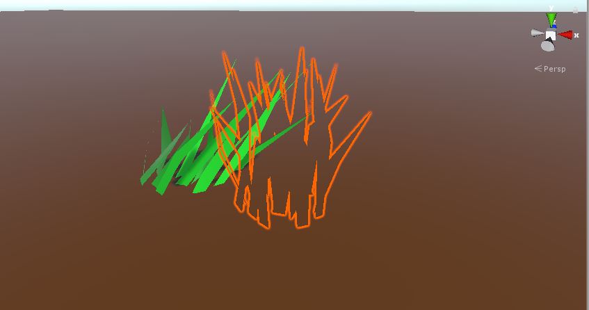
In the Scene and Game view, you should notice that if we change the OffsetX property, our Grass object shifts… or rather its vertices have!
Select the object in the Hierarchy and you can see the highlighted outline where theoriginal Transform normally would appear.
The final MeshRenderer has shifted in world X because of our Shader Graph’s Add node. Experiment with different OffsetX values to confirm this for yourself.
MOTION WITH SINE WAVES
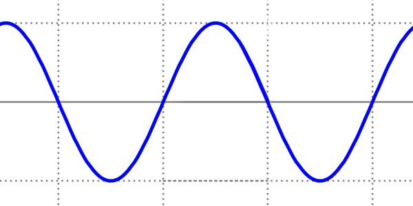
We want our grass to animate, so a static shift doesn’t help our cause much, but we can use some trigonometric functions to add some wave-like motion.
Instead of using a static value, let’s drop in a Sine wave.
Delete the OffsetX node and OffsetX property since that was just for testing.
Let’s instead replace them with a Time node (Create Input > Basic > Time) and a Sine node (Create Node > Math > Trigonometry > Sine).
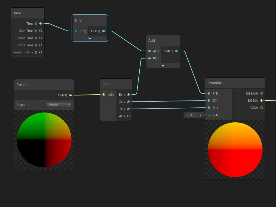
Connect these together like this and you should notice that our preview thumbnails start moving back and forth! Our sine wave is offsetting the x position of our vertices.
Cool! Now we have some motion. Save the graph to see the effect on our actual GameObject.
In the Scene and Game view, you should see our grass oscillate back and forth 1 unit in x in each direction.
We’re adding a Sine wave to the object’s position, so you will see the entire mesh rocking along the x axis.
If you want to vary the speed and timing of the movement, you can add multipliers to the Graph.
Create a couple of Vector1 properties on the Blackboard, WindFrequency and WindAmplitude. Default these to 0.5 and 0.25. Drag these into the work area.
Insert a couple of Multiply nodes (Math > Basic > Multiply) and connect those before the Sine node and before the Add node. Our properties will now modify the sine wave motion.
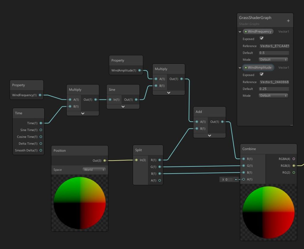
The first Multiply will control the timing (smaller values making the motion slower). The second Multiply will control the Amplitude (smaller values reduce how much the mesh moves). The final motion is subtle, so we definitely want to keep relatively small numbers here.
MASKING WITH UVs
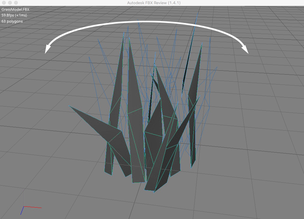
Of course, we don’t want to move the entire mesh. We want the bottom of the mesh to stay put on the ground and bend each blade of grass more and more as we travel upward.
The tip of the grass model will get the maximum displacement. The bottom of the grass model will get zero displacement. And everything in between will interpolate.
If you examine the UV Layout of our mesh with an external 3d application (e.g. Maya, Blender, etc), you’ll see that the bottom of the grass vertices fall near where the U value is 1 on the right side of texture space.
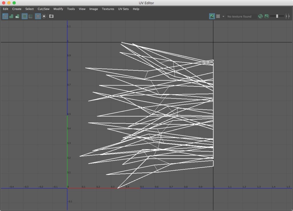
We can use this UV Layout to our advantage. Let’s use the UV coordinates of our mesh to mask out how much we shift the vertices.
Drop in a UV node into our Graph (Create Node > Input > Geometry > UV)
The U coordinate is captured on the red channel and the V coordinate is captured on the green channel (the blue channel technically contains the W coordinate, but that’s not really used in this case).
We are only concerned about the U coordinate in this example, so we can selectively grab the first output of the UV node using another Split node (Create Node > Channel > Split).

Let’s blend between the model’s original vertex positions and its shifted vertex positions (with the extra sine wave added on top). We can use the U coordinate to determine how to blend the two sets of positions.
Create a Lerp node (Create Node > Math > Interpolation > Lerp) and connect it in between the Combine and Transform nodes.
For the original vertex positions, we can either re-use the Position node we already have or if it’s a little easier to read, we can just copy and paste it. Drop that right next to the Lerp node to keep the graph neat and clean.
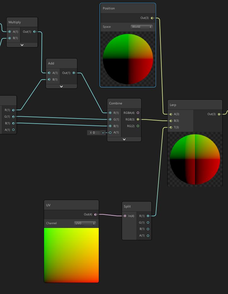
The original world space position goes into the A input. And our shifted world space position goes into the B input. The U coordinate goes into the T input. This blends between the two sets of positions based on where the vertex falls in UV space.
That almost works. There’s one problem though. We need the interpolation to go the other direction.
This current setup makes the tip of the grass stay fixed in space while the base of each blade of grass moves. We want the bottom of the grass to stay in one place.
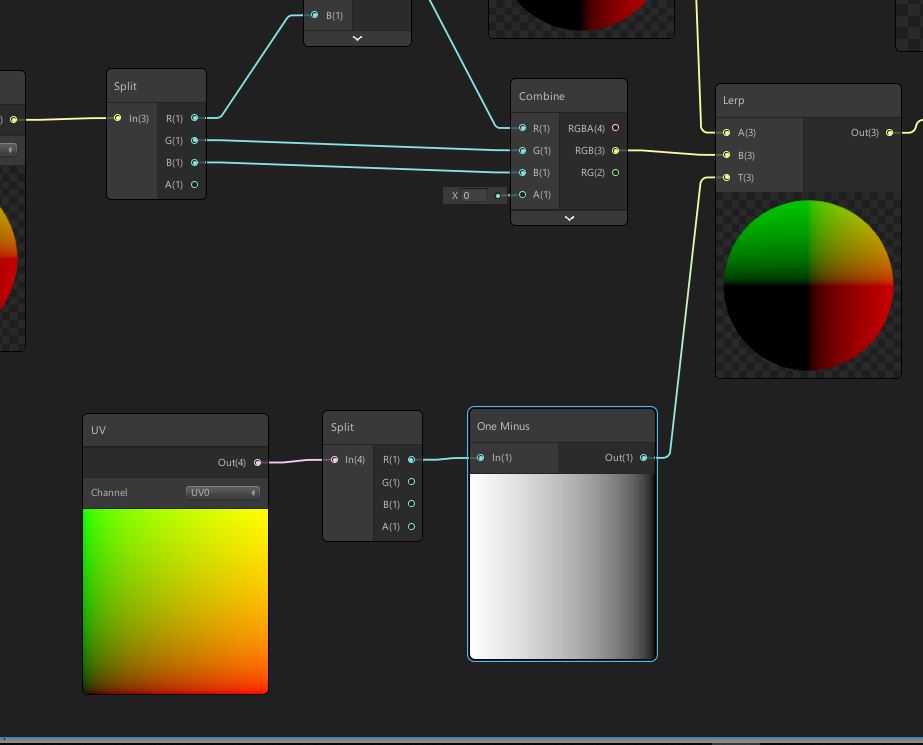
We can fix that with a OneMinus node. If subtract our U coordinate from a value of 1, that should fix it.
Now our grass model’s vertices will move depending on where they are in UV space. If a vertex is near the bottom of a blade of grass, it shouldn’t bend at all. If it’s near the top, it should receive the maximum amount of displacement.
WRAPPING UP
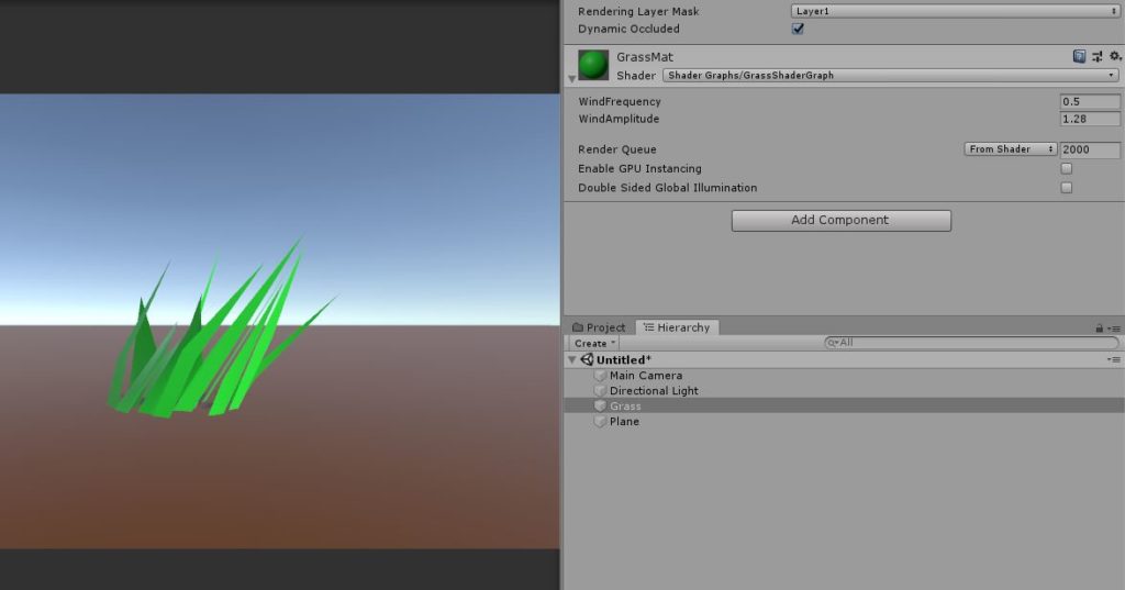
Pretty neat, huh? You can adjust the WindAmplitude and WindFrequency to modify the range and speed of the motion. Then you can duplicate the Grass prefab and start laying out a denser field of grass.
Our effect is pretty basic, of course, and it’s odd how every blade of grass sways exactly like the one next to it. But it’s a start! We now have a general method for making a piece of geometry sway back and forth.
Adding a few extra nodes can make the motion a bit more organic and less cartoony. We haven’t covered the various noise nodes in Shader Graph yet, so we’ll have to revisit that in a future post.
We’re hoping that this basic example gives you some ideas on what you can do with the Position node. With a little bit of extra work, you can modify this for waving flags or bouncing water waves — and remember this is all procedural animation done with shaders.
Stay tuned! We’ll have more Shader Graph fun in future articles!